Logic Circuit Design with Logisim
Objectives
-
Learn to design and debug simple logic circuits in Logisim
-
Gain experience in designing and debugging logic circuits
Preamble
If you are not familiar with the circuit design software Logisim, start by familiarizing yourself with this tool by following this “ tutorial ” and these “ tips ”.
This lab is has three exercises:
- Rotation circuit — particularly useful for the ALU part of the project
- State machine circuit — the processor is simply a big finite state machine
- Pipelining circuit — a very simplified version of hardware parallelization in a processor
To test your implementations of the circuits, run the following commands in a terminal:
$ cd path/to/the/directory/lab7
$ chmod +x run_test.sh # <-- to do the first time only
$ ./run_tests.sh # <-- run this each time you want to test your circuits
This script copies your ex?.circ circuits into the testing/circ_files/ folder, runs the ex?_test.circ test circuits with different inputs, and compares the outputs of your circuits to the expected results. Therefore, do not change anything in the lab7/testing folder. You are encouraged, however, to look at the content of this folder to enhance your understanding of logisim and how testing of your circuits is done. This will be very useful for your mini-project!
CAUTION
Your ex?.circ files must fit into the provided ex?_test.circ harnesses. This means that you must be careful to NOT rearrange the inputs or outputs of the circuits. If you need more space, use tunnels!
To check that your changes have not broken the input/output mapping between your circuit and the 'harness' circuit, open the ex?_test.circ file in Logisim and make sure there are no connection errors (i.e. no red/orange wires).
Exercise 1: (rotation from right-to-left)
With splitters and multiplexers, you need to implement a non-trivial combinational logic circuit: rotr, which stands for « Rotate Right ». The idea is that rotr A, B will « rotate » the bits of input A from right to left B bits times. So, if A is 0b1011010101110011 and B is 0b0101 (5 in decimal), the output of the rotr circuit will be 0b1001110110101011. Note that the rightmost 5 bits have been extracted from the right end of the value of A and injected back into its left end. In RTL, the operation looks like this R = A >> B | A << (16 - B).
Using Logisim, implement in ex1.circ the subcircuit named rotr with the following inputs:
-
A(64-bit), the 64-bit data to rotate -
B(6-bit), the amount of rotation (why 6 bits?)
The output of the circuit must be the value of input A rotated from right-to-left by B positions. You are NOT allowed to use Logisim shift components in your solution. However, any other combinational components (MUX, constants, logic gates, adders, etc.) are allowed. Your solution must NOT also use a clock or timed elements, such as registers.
Hint 1: Before you start, you need to think about how you could break down this problem. Consider using subcircuits (skeletons already provided)!
Hint 2: The RTL representation of rotr given above does not necessarily mean that it is the best way to implement the solution to the problem. Think about the bits of the input B and think about how to use splitters efficiently! Can you do something with the binary representation of B? As a reminder, a 1 can represent an ON signal and a 0 will represent an OFF signal. Let’s say we want to rotate 9 times. 9 is 1001 in binary, or 1 * 8 + 0 * 4 + 0 * 2 + 1 * 1. Can you use this to create a clean circuit? Use the rot* subcircuit provided in ex1.circ!
Exercise 2 : (Faulty traffic lights)
A state machine (i.e. automaton) is a very versatile tool used to develop systems for all kinds of applications. In this exercise, we model, as a finite state machine, the traffic lights used in road traffic control. In this sense, we use a register to store the state of the automaton we are currently in, and a combinational logic to link the input and current state of the automaton to the output and the next state of the machine.
The automaton has three (3) states:
. RED encoded by the binary value 00 . GREEN encoded by the binary value 01 . ORANGE encoded by the binary value 10
The input is a “trigger signal”. When it is at (1), the automaton moves to the next state (i.e. our traffic light changes color). When equal to (0), the automaton loops in the current state (i.e. our traffic light keeps the same color). Such a trigger signal could be periodic, controlled manually or by another system (such as a traffic monitoring system).
The output from the automaton circuit is the same as its next state (see below).
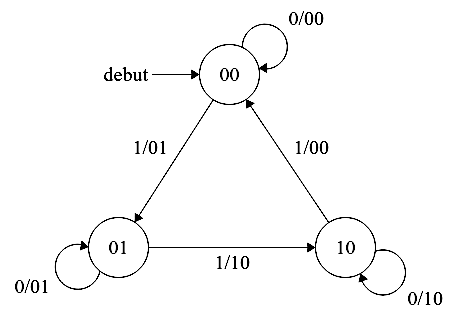
So, the traffic lights go on as follows: RED ⟶ GREEN ⟶ ORANGE ⟶ RED.
Here is the truth table associated with our automaton
| Current state | Input | New state |
|---|---|---|
| 00 | 0 | 00 |
| 00 | 1 | 01 |
| 01 | 0 | 01 |
| 01 | 1 | 10 |
| 10 | 0 | 10 |
| 10 | 1 | 00 |
Tasks
A faulty implementation of the automaton is provided in the circuit ex2.circ. Your task is to fix this circuit so that it works properly. In particular, three bugs have been inserted into the following (sub)circuits:
- Bit_0_State: Look at the wire colors and see if something is wrong here.
- Bit_1_State: Again, check the wire colors. Does a connection look off? Use the truth table to spot the problem.
-
FSM: The input pin
clkis driven by a clock signal provided by the test harnesstesting/circ_files/ex2_test.circ. You can manually simulate this signal by clicking on theclkpin after selecting the ‘Poke’ tool (i.e. the icon in the toolbar). You can also use this tool to check the status of the wires and other pins in the circuit. This should help you see why our PLC implementation is not behaving as expected.
Note that there are no errors in the FSMLogic or Helper subcircuits. The Helper subcircuit is used to map the PLC states to the RED, GREEN, and ORANGE LEDs; and to provide a trigger signal. You do not need to examine the operation of this circuit for this exercise, but feel free to do so ![]() .
.
A correct circuit works as shown below
Exercise 3 : (Datapath)
For this exercise, you can assume that the registers are initially set to zero. The provided starter file ex3.circ should include a subcircuit called non_pipelined that looks like this:
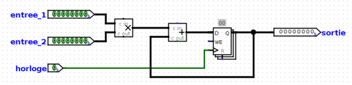
This circuit takes two values as inputs, multiplies them together, and then adds the result to the current state value. We would like to improve the performance of this circuit and make it run at a higher clock frequency. In this sense, it is required to implement in the pipelined subcircuit the parallelized version using a two-stage pipeline:
- one stage for multiplication and
- one stage for addition, in that order.
Your pipelined circuit will be considered “correct” if-and-only-if the outputs produced by this circuit match the sequence of outputs that the non_pipelined version would emit, except for an additional leading zero.
Explicitly, the sequential version provided in the non_pipelined subcircuit produces the following sequence of numbers: [3, 5, 1, 2, 4, -1, 0, 0, …]. So, your pipelined circuit will be considered “correct” if it emits the following sequence of numbers: [0, 3, 5, 1, 2, 4, -1, 0, 0, …].
Hint: To implement the pipelined version, you will need to introduce “something” to hold the intermediate value of the computation between the pipeline stages.