Tips for Logisim
Tip #1: ‘zoom’ function in Logisim
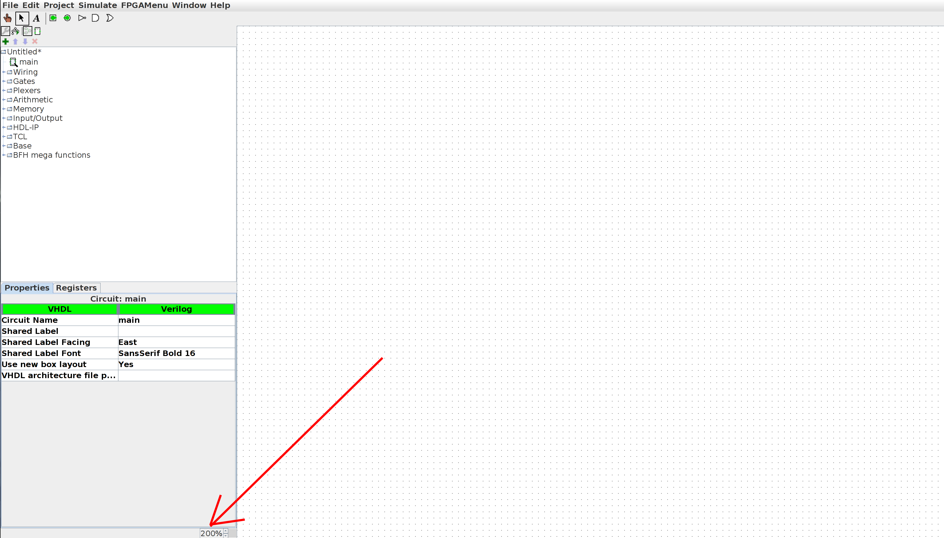
This feature allows you to zoom in on circuits and will be very useful, especially when designing very complex circuits. This functionality is accessible from the lower left corner of the Logisim window (see below).
Tip #2: How to connect a splitter to a logic gate
To connect a splitter to a logic gate, the naive approach is to connect the wires one by one as shown in the left image. It’s easier to glue the logic gate to the splitter and then move the gate away from the splitter to build the connecting wires.
 |
 |
|---|---|
| naive method | quick method |
This tip is very useful when you have a lot of inputs to connect (like 32 inputs for example). You can also use this technique to connect splitters with other splitters.
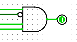
Tip #3: Invert an input of a logic gate
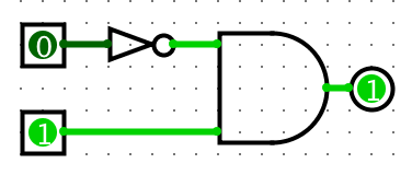
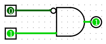
Sometimes we need to invert an input to a logic gate. In this case, instead of inserting an additional ‘NOT’ gate between the input and the circuit, we ‘add’ a small circle to invert the logic gate input.
 |
 |
|---|---|
| inserting a ‘NOT’ gate | inserting a ‘circle’ |
To add a circle, follow these steps:
-
Enable the “Select tool” mode (i.e. click on the black arrow at the top left of the window).
-
Select the logic gate to which you want to add the circle(s).
-
In the properties tab (bottom left section of your window), choose the input(s) to invert.
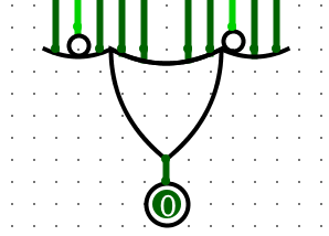
Tip #4: Change the appearance of a logic gate
You can modify the orientation (i.e. North, South, East or West) and the number of inputs of a logic gate. This allows you to change the appearance (and functionality) of the gate. You can also change the “Data Bits” attribute (i.e. the width) to indicate how many bits each entry will have.
 |
 |
|---|---|
| 4-input AND gate facing east | 10-input OR gate facing south |
To change the appearance of a logic gate, follow these steps:
-
Enable the “Select tool” mode (i.e. click on the black arrow at the top left of the window).
-
Click on the gate whose appearance you want to change.
-
In the properties tab (bottom left section of your window), edit the “Facing” and “Appearance” settings as desired.
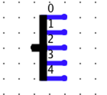
Tip #5: Reverse the Splitter Pins
Sometimes it is better to reverse the splitter pins to have a less cluttered logic circuit. This is especially useful when you have a splitter with a lot of pins to reverse.
 |
 |
|---|---|
| naive method | quick method |
Right-click a splitter and choose “distribute ascending/descending” to change the distribution.
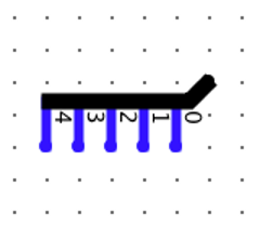
Tip #6: Change the appearance of a Splitter
You can change the orientation of a Splitter (North, South, East or West directions) as well as its appearance (Left-Handed, Right-Handed, Centered or Legacy). Try playing with these different attributes to identify which ones look best for your circuit.
 |
 |
|---|---|
| “Right-handed” separator facing south |
“Centered” separator facing east |
To change the appearance of a Spliiter, follow these steps:
-
Enable the “Select tool” mode (i.e. click on the black arrow at the top left of the window).
-
Click the Splitter whose appearance you want to change.
-
In the properties tab (bottom left section of your window), edit the “Facing” and “Appearance” settings as desired.