Exception mechanisms in MIPS
Introduction
Conditional and jump instructions change the flow of execution in a program. Exceptions are events that occur during program execution and also change the flow of execution.
An exception is said to be synchronous if it is caused by an instruction in the current program. Arithmetic exceptions (division by zero, overflow, …), access to invalid memory addresses are examples of synchronous exceptions. An exception is said to be asynchronous if it is caused by an I/O device (keyboard, mouse, …). This type of exception is not related to program execution and is also called hardware interrupts.
When an exception occurs, the current program is suspended and control is transferred to an exception handler to process the exception that occurred. Once the exception is handled, control is returned back to the program which resumes its execution from where it has been suspended. In contrast to traditional function calls, the exception handler is a “suddenly called” procedure (without parameters or return value).
There are two modes of program execution in a MIPS processor. The user mode and the supervisor mode (aka kernel mode). Standard programs run in user mode. The processor switches to supervisor mode when an exception occurs. The exception handling mechanism in MIPS is implemented by an auxiliary coprocessor called: Coprocessor0. This device contains several registers which store information about the exception.
| vaddr ($8) | Contains the memory address whose access is invalid. Caused by a load, store, or fetch instruction. |
| status ($12) | Interruption mask (see below). |
| cause ($13) | Exception type and pending interrupts (see below). |
| epc ($14) | Holds the instruction address (i.e. content of $pc) when the exception occurred. |
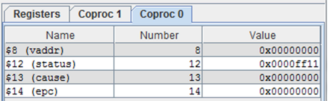
In MARS, the values of the registers: vaddr, status, cause and epc are accessible from the Coprocessor 0 tab.
Examples of code to generate software exceptions are shown below. The first example initializes the register $t0 with 0x7fffffff and $t1 with 1. The addu instruction performs an unsigned addition and therefore ignores the overflow. However, the add instruction performs a signed addition and since there is an overflow here, this instruction will cause an arithmetic overflow exception. In the second example, an attempt is made to store data at an illegal address in memory. In the third example, we are trying to read a word from a misaligned address in memory. And in the last example, the very effect of inserting a breakpoint (i.e.a break instruction) into a program (while debugging) will cause an exception.
  # Arithmetic overflow exception
  li     $t0, 0x7fffffff    # $t0 = MAX_INT
  li     $t1, 1             # $t1 = 1
  addu   $t2, $t0, $t1      # Ignore Overflow
  add    $t3, $t0, $t1      # Detect Overflow
  # Invalid address exception
  # cannot save to address 4 in memory
  li     $t0, 4
  li     $a0, 5
  sw     $a0, ($t0)

  # Unaligned memory address exception
  .data
  arr: .word 12, 17
  . . .
  la     $t0, arr
  lw     $t0, 1($t0)
  # Breakpoint exception
  # caused by a "break" instruction
  .text
  . . .
  break
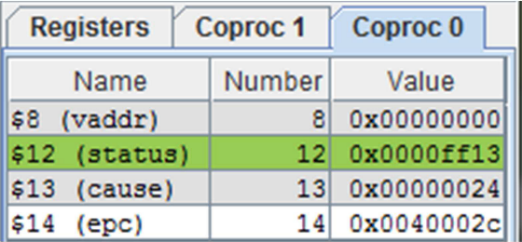
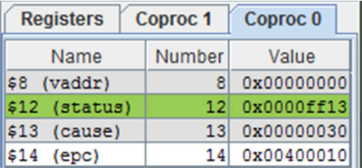
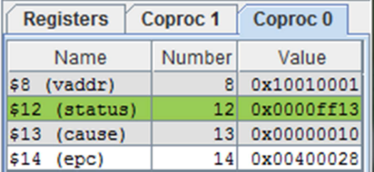
The screenshots on the right above show the states of Coprocessor0 registers when exceptions occur. The exception program register epc ($14) stores the address of the instruction when the exception occured. The value of epc in the first example is 0x00400010. This value is the address in memory of the add instruction that caused the arithmetic overflow. In the second example, the epc register contains the value 0x0040001c, which corresponds to the address of the sw instruction that attempted to write to an illegal address in memory. In the third example, epc contains the value 0x00400028, which is the address of the lw instruction that generated the misaligned address exception.
If a read, write, jump, or branch instruction creates an exception, then vaddr ($8) register will contain the invalid address that caused the exception. Continuing with the examples above, the illegal write address that caused the exception in the sw instruction example is vaddr = 0x00000004, and the misaligned address in the lw read instruction example is vaddr = 0x10010001.
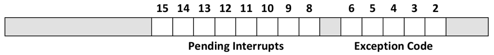
The cause ($13) register provides information (i.e. exception code) about the reason of the exception and any pending interrupts, if any. The exception code is stored in bits 2 through 6 of the cause register.
 |
|---|
| cause register |
The MIPS architecture defines numeric codes (values) for different types of exceptions. Some of these codes are listed below.
| Code | Name | Description |
|---|---|---|
| 0 | INT | Hardware Interrupt |
| 4 | ADDRL | Address error exception caused by data loading (load) or fetching (fetch) instructions |
| 5 | ADDRS | Address error exception caused by a data save instruction (store) |
| 6 | IBUS | Bus error while fetcing an instruction |
| 7 | DBUS | Bus error while loading or saving data |
| 8 | SYSCALL | A system call exception caused by a syscall instruction |
| 9 | BKPT | Breakpoint exception caused by a break instruction |
| 10 | RI | Exception due to “reserved” instruction |
| 12 | OVF | Overflow exception |
| 13 | TRAP | Exception caused by a trap instruction |
| 15 | FPE | Floating point arithmetic exception |
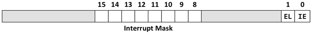
The status ($12) register controls interrupt permissions. Bit 0 (IE - Interrupt Enable) enables or disables interrupts globally. Bit 1 is called the Exception Level. This bit is normally 0 unless an exception/interrupt occurs, in which case it is set to 1. The **interrupt mask is an 8-bit field. One bit for each of the six hardware and two software interrupt levels. When a mask bit is 1, interrupts at that level are autorised. When a mask bit is 0, the interrupts associated with that level are masked (i.e. disabled). When an interrupt occurs, the associated bit in the cause register (interrupt pending) is set even if the mask bit is cleared. When an interrupt is pending, it will be processed by the processor once its mask bit is set.
 |
|---|
| status register |
Coprocessor0 instructions
When an exception occurs, the processor switches to supervisor mode. The Coprocessor0 registers are accessible only when the processor is in this execution mode.
The contents of the Coprocessor0 registers can be transferred to/from this device using the mfc0 and mtc0 instructions, respectively. It is also possible to transfer data between the Coprocessor 0 registers and memory using the additional lwc0 and swc0 instructions.
| Instruction | Description |
|---|---|
mfc0 rd, c0src |
Copy register c0src from Coprocessor0 to destination register rd |
mtc0 rs, c0dst |
Copy source register rs to Coprocessor0 register c0src |
lwc0 c0dst, addr |
Reads a word from memory and copies it into the c0dst register |
swc0 c0dst, addr |
Saves the content of registerc0src to memory |
eret |
Set EL = 0 (switch to user mode) and return: $pc = $epc + 4 |
The MIPS architecture also defines special instructions that cause exceptions and switch the processor from “user mode” to “supervisor mode”. These are the trap, break, and syscall instructions:
| Instruction | Description |
|---|---|
teq rs, rt |
Generates a trap exception if registers rs and rt are equal |
tne rs, rt |
Generates a trap exception if rs is different from rt |
tlt rs, rt |
Generates a trap exception if rs is less than rt |
| . . . | other trap instructions exist |
break |
Generates a Breakpoint exception |
syscall |
Generates a “system call” exception. |
Trap instructions (teq, tne, …) generate the TRAP exception (code 13). The break instruction generates the breakpoint exception (code 9), and the syscall instruction triggers the system call exception (code 8).
Exception Handler
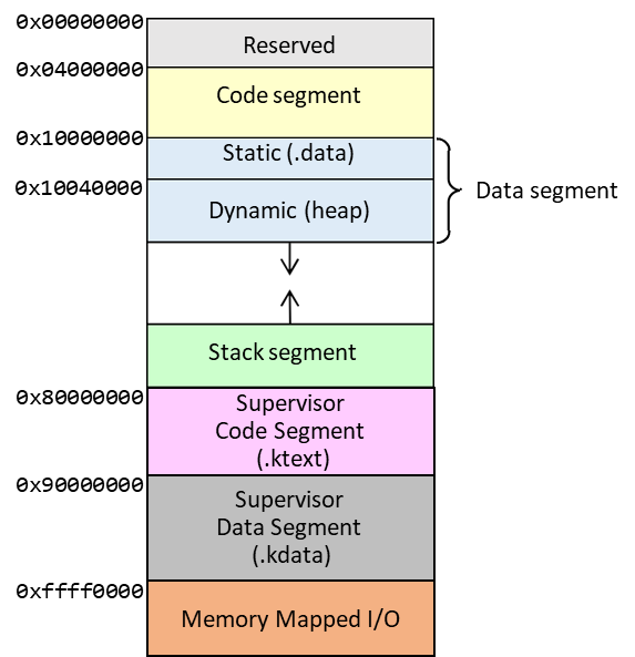
The memory layout in a MIPS architecture is shown below. The operating system appears in the top half of the address space, accessible only when the processor is running in supervisor mode. The supervisor code segment starts at address 0x80000000 and the supervisor data segment starts at address 0x90000000. The last segment of the address space is mapped (see paragraph below) to the I/O devices starting at address 0xffff0000.
In MIPS, when a function is called using the jal instruction, control is transferred to the address provided by the instruction and the return address is stored in $ra register. In the case of an exception/interrupt, there is no explicit call… when an exception occurs, control is transferred to the fixed address 0x80000180. The exception handler must be implemented at this address. The return address from the exception cannot be stored in $ra because it will modify a return address that was placed in that register before the exception occurred. It is the epc register in Coprocessor0 that plays the role of the $ra register when an exception occurs (i.e. the epc register stores the address of the instruction that was executing when the exception occurred).
An exception handler must perform five steps:
- Save the standard processor registers before modifying them in the exception handler.
- Identify the exception that occurred by examining the contents of the Coprocessor0 registers.
- Execute the exception-specific routine, usually via a branch table.
- Restore all possibly modified standard registers in the exception handler.
- Continue execution of the program in “user mode” or terminate the program if it cannot be restarted
The exception handler must preserve the value of any registers it might modify so that execution of the interrupted program can resume at a later time. The MIPS architecture reserves registers $26 and $27 (i.e. $k0 and $k1) for use by the exception handler. The handler can modify these two registers without having to save them first. Other processor registers must be saved in memory before being modified in the exception handler.
For example, the exception handler shown below saves registers $at, $a0, and $v0 in the supervisor data segment (at address _regs) before modifying them, and restores their contents at the end of the routine before ereturning to the suspended program. In fact, since the epc register contains the address of the instruction at the time the exception occurred, the return address must be incremented by 4 to avoid executing the same instruction again.
Here is the complete routine. The program displays the address of the instruction that caused the exception and its code.
# Exception Handler starts here
.ktext 0x80000180
move $k0, $at                     # $k0 = $at
la $k1, _regs                     # $k1 = address of _regs
sw $k0, 0($k1)                    # save $at
sw $v0, 4($k1)                    # save $v0
sw $a0, 8($k1)                    # save $a0

la $a0, _msg1                     # $a0 = address of _msg1
li $v0, 4                         # $v0 = service 4
syscall                           # Print _msg1
mfc0 $a0, $14                     # $a0 = EPC
li $v0, 34                        # $v0 = service 34
syscall                           # print EPC in hexadecimal

la $a0, _msg2                     # $a0 = address of _msg2
li $v0, 4                         # $v0 = service 4
syscall                           # Print _msg2
mfc0 $a0, $13                     # $a0 = cause
srl $a0, $a0, 2                   # shift right by 2 bits
andi $a0, $a0, 31                 # $a0 = exception code
li $v0, 1                         # $v0 = service 1
syscall                           # Print exception code

la $a0, _msg3                     # $a0 = address of _msg3
li $v0, 4                         # $v0 = service 4
syscall                           # Print _msg3

la $k1, _regs                     # $k1 = address of _regs
lw $at, 0($k1)                    # restore $at
lw $v0, 4($k1)                    # restore $v0
lw $a0, 8($k1)                    # restore $a0

mtc0 $zero, $8                    # clear vaddr
mfc0 $k0, $14                     # $k0 = EPC
addiu $k0, $k0, 4                 # Increment $k0 by 4
mtc0 $k0, $14                     # EPC = point to next instruction

eret                              # exception return: PC = EPC

# kernel data is stored here
.kdata

_msg1:   .asciiz    "\nException caused by instruction at address: "
_msg2:   .asciiz    "\nException Code = "
_msg3:   .asciiz    "\nIgnore and continue program ...\n"
_regs:   .word 0:3               # Space for saved registers
Memory mapped inputs/outputs
In any computer, the input and output devices are located outside the processor chip. A MIPS processor communicates with the I/O devices using a technique called memory-mapped I/O.
With memory-mapped I/O, there is no need to add additional instructions to the MIPS instruction set. Any lw or sw instruction with an effective address equal to or greater than 0xffff0000 will not access main memory but an address reserved for accessing the I/O device registers. The I/O device controllers are connected to the system’s I/O bus as shown below.
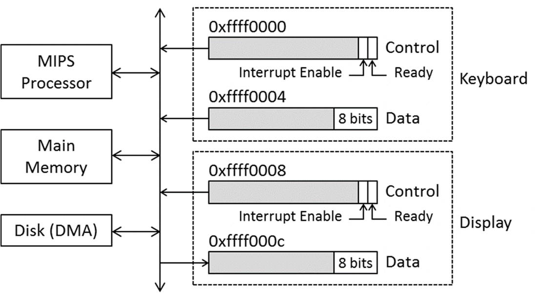
When a key is pressed on the keyboard, the Data register stores the associated character and the Ready bit in the Control register is set. The following MIPS code provides an example of memory-mapped access to the keyboard controller registers using the polling method:
li     $t0, 0xffff0000      # Address of keyboard control register
li     $t1, 0               # Initialize wait_counter = 0

wait_keyboard:

lw     $t2, ($t0)           # Read the keyboard control register
andi   $t2, $t2, 1          # Extract ready bit
addiu  $t1, $t1, 1          # wait_counter++ (counts iterations)
beqz   $t2, waitkeyboard    # loop back while not ready
lw     $a0, 4($t0)          # Get character from keyboard
The frequency of typing characters on the keyboard is very slow compared to the speed at which a processor can execute instructions. Typically, millions of instructions are executed in the period of time a key is pressed in succession. In our example, the $t1 register keeps track of the number of iterations performed in the wait_keyboard loop before a key is pressed. The lw instruction at the end of the loop fetches the character from the keyboard’s Data register, which also clears the ready bit. A MIPS program can only read the contents of the keyboard’s data register. Writing to this register has no effect.
Communication with the graphics card can be done in a similar way via polling. The display registers are mapped to addresses 0xffff0008 and 0xffff000c. Indeed, as seen in the code below, as long as the ready bit of the Control register is clear, the routine will continue to loop through that register. We should not write characters to the Data register until the display is ready to receive them. The display controller clears the ready bit when a character is written to the Data register and sets it to 1 again once the character is displayed.
li    $t0, 0xffff0008      # Address of display control register

wait_display:

lw    $t2, ($t0)           # Read the display control register
andi  $t2, $t2, 1          # Extract ready bit
beqz  $t2, wait_display    # loop back while not ready
sw    $a0, 4($t0)          # Send character to display
The main disadvantage of the polling method is that it keeps the processor busy, wasting millions of cycles before the I/O device (such as the keyboard) is ready. An alternative method is to use interrupts. These can be enabled for the keyboard by setting the Interrupt Enable bit in the keyboard’s Control register as follows:
li  $t0, 0xffff0000   # Address of keyboard control register
li  $t1, 2
sw  $t1, ($t0)        # Enable keyboard interrupt
When a key is pressed, the keyboard sends an interrupt signal to the MIPS processor and initialises the cause register to the value 0x00000100. Bit 8 in the cause register is set to indicate that the keyboard has interrupted the processor. In order for the character entered on the keyboard to be used by the running program, an interrupt handler must be written to read the character from the keyboard Data register and return it to the program.
Recent I/O device controllers (such as hard drives and network cards) use DMA (Direct Memory Access) to transfer blocks of data directly between the device and memory. As controllers become more complex, more than two registers are associated with each device controller. Typically, the I/O device manufacturer provides programmers with a manual (English Data sheet) on how to properly communicate with that device’s controller.